Pages
Welcome - Please Read
Welcome. I wanted to provide stripboard layouts I've made to help people new to electronics and even the more experienced get into different aspects of electronics.
I verify the layouts before I post them.
My Facebook Group: www.facebook.com/StripboardLayouts - Please Add For Updates!
My Twitter Thing: @InSonicBloom
I verify the layouts before I post them.
My Facebook Group: www.facebook.com/StripboardLayouts - Please Add For Updates!
My Twitter Thing: @InSonicBloom
Showing posts with label 555. Show all posts
Monday, 23 March 2020
20 Second Handwashing Timer (for Covid-19) stripboard layout
quite a simple project, during the Covid-19 coronavirus outbreak, one of the pieces of advice we've been given is to wash our hands for 20 seconds. so here's a timer circuit to help you do that.
"sw" is a push-to-make momentary switch, once you press the button, the LED illuminates for about 25 seconds (I added a few seconds to the timer to allow time to put soap on your hands). then just wash your hands till the LED goes off.
pretty good way to make sure your kids are washing their hands for long enough.
Stay safe.
before it was deployed to the bathroom
Friday, 17 July 2015
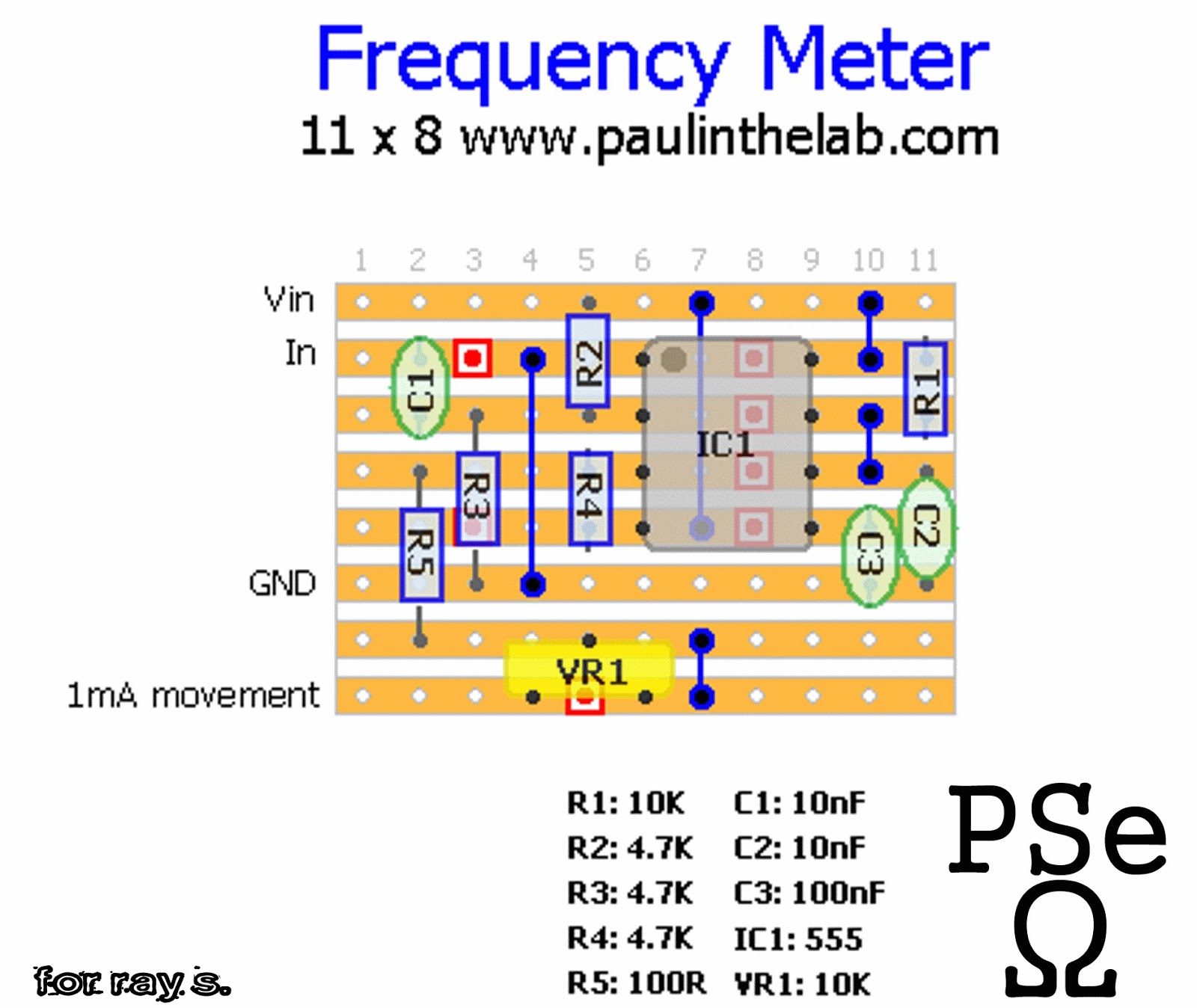
Frequency Meter Stripboard Layout
I built this as a rough frequency meter to make sure a bunch of oscillators were oscillating in the right ballpark frequency.
it uses the lovely 555 timer IC.
it responds best to squarewave signals (maybe triangle too, I forgot to test it with triangle waves)
Thursday, 19 June 2014
Ellas Stylophone Stripboard Layout
I have a 2 year old niece called Ella and I wanted to make her something - so I thought I would make her a Stylophone.
NB: there were a couple of errors due to me somehow pressing the "up" button in "DIY layout editor" after I had built this but before I had rendered the image. these errors have been corrected
the original error was; the "tuning board" was listed as being connect to pin8 of IC2 - however it should be connected to pin 7 of IC2
I also missed out "R4" in the schematic (cause I drew the schematic after building it)
![]() |
| Me and Ella |
Thursday, 27 February 2014
Atari Punk Console Stripboard Veroboard Layout
Another quick one. A favorite among beginners - originally by Forrest Mims
I got an email this morning asking to check over a layout he'd found and also how to add a volume pot so I just did a new layout, built it and made some stupid noises for half an hour and now I'm posting it here.
this is obviously the version that is adapted to use 2 single 555 timers rather than 1 dual 556 timer but it's the same.
have fun.
Wednesday, 2 October 2013
Logic Pulse Generator - Logic Pulser Stripboard Veroboard Layout
Often with projects that uses Logic devices such as previous projects like the devils drone sequencer or the Sound Activated Dancing LEDs you need to create a clock signal to make the logic transition from one state to the other. you don't want to have to deal with the clock (or oscillator) part of the circuit in the experimentation stage so you need something that is capable of creating a clock signal. This is just that piece of test gear.
it also uses the same power supply you're using to power the Logic ICs in question.
here is an example of a commercial version http://uk.rs-online.com/web/p/needle-point-probes/5375163/?origin=PSF_437277|alt
aswell as the layout and schematic - I have included some oscilloscope pictures of what it actually does.
Sorry if my explanation is a little off today in the making sense department - I am suffering from cluster migraines and one of the symptoms is Aphasia. the important thing is that the actual layout and circuit are correct - which as you can see - is the case!
![]() |
| As you can see I have soldered a nail to the pulse output - I've found this is the ideal probe |
Wednesday, 11 September 2013
Devils Drone Sequencer Veroboard Stripboard Layout
This has taken some time to design and it's not perfect but it sounds pretty cool (As you can hear from the sample) it follows on from the devils triangle I did earlier this year ( Found HERE and no you don't have to build that to make this work!)
This is quite a big project and as you can hear I have built it using the stripboard layout provided (as I do with all my layouts) so take your time because I really can't spend lots of time answering why things don't work. The truth is that unless you have the board in front of you there is no possible way to troubleshoot things. But if you take it slowly it should be good.
also don't forget to check out the "tips and troubleshooting" page above
I would also recommend not to do this if you're in-experienced
Sunday, 28 July 2013
Poor Mans Audio Signal Generator Stripboard Veroboard Layout
this is something I made in school 15 odd years ago. you had to take a square wave, use a passive filter network to convert the signal to triangle and sine - this also has square and integrator waveforms. it's quite good up to 1 KHz but after that it starts to clip and go funny but it's more than adequate as an extremely cheap audio signal generator using 2 transistors and 1 LM555 timer IC - if you've gone through alot of my projects you'll notice how useful this IC is by now.
I have done another signal generator project that uses a proprietary ICL8038 IC Project can be found HERE which is more fully featured as far as project function generators go but the IC can be costly in certain places where as you can go on the grey market (IE eBay china sellers) and pick up hundreds of them for next to nothing.
Wednesday, 17 July 2013
Temperature Controlled Fan Controller Stripboard Veroboard Layout
I built this for 2 things - 1. my computer is getting a little hot and I like quiet for as much as is possible so having a little automatic controller turning on a few fans when it gets too hot is ideal for me. and 2. my homemade power supplies could do with fans and again I don't want them running all the time but with this particular temperature sensor LM35DT as it is a TO-220 package you can screw it to the heatsink you have your regulators on (with the usual isolation of course) so the fan only runs when the regulator gets abit hot.
(v)R3 controls at which heat the fan will turn on at however it is a little tricky to calibrate so it will be a case of trial and error unless you have known heat sources.
I also used a TLC071 OP-AMP for a couple of reasons 1st. it is a single supply op-amp so I didn't have to piss about with dual supplies etc. and 2nd I got it free from Texas Instruments excellent sample service
I used a TIP41A because that's what was nearest to my hand. I know the schematic says TIP41C but it doesn't really matter - the letter designations just refer to the voltage the transistor can handle and none of them go below 40 volts so use whichever you can get or even any similar NPN power transistor will be fine.
Saturday, 19 January 2013
Floating Power Supply For DVM Panel Meters Stripboard Veroboard Layout
this was another one done out of necessity really.
I needed to power a panel meter from the same supply as I was measuring.
I actually didn't have the meter to test it with however it powered a cheap Digital Multimeter which I imagine takes up more current than a panel meter.
I also tried to make it small enough to be glued onto the back of the panel meter.
Thursday, 10 January 2013
LED Crossfader Stripboard Veroboard Layout
I was going to use an op-amp at first but I thought a 555 would yield a more consistent result
Friday, 30 November 2012
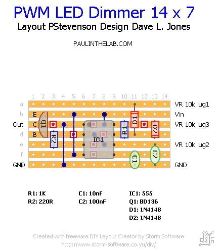
PWM LED Dimmer Stripboard VeroBoard Layout (Orig. By Dave L. Jones)
Dave Jones did a cool little circuit using a 555 to dim the LEDs on his Mantis microscope. Obviously this little circuit has a lot of uses so I thought I would make a little stripboard layout for it.
There isn't much to say about it as it has already been covered in his video (linked below)
so here you go.
Thursday, 4 October 2012
Flux Capacitor LED Decoration Stripboard Veroboard Layout
for fans of Back To The Future - or LEDs
I know this isn't exactly like the real thing however that would involve crux tubes and so on and I doubt many people who read my site want to piss about with 10,000 volt supplies. Anyway it's pretty much for my halloween/christmas/bonfire night decoration collection.
as you can see I have included a layout for the actual display board, although it looks like the LEDs maybe abit too spaced out, in practice they wouldn't fit when they are closer together. However should you just want to use the display board I think that each transistor can drive quite a few LEDs (I think the 2N3904s are rated at 100mA)
As it stands the circuit draws roughly 5mA
The last thing I want to mention is the odd value electrolytic (well odd to some) it is 470nf however you can use a none polarized version it just happened that I have both kinds and the electrolytic takes up less space
I also included a little video to show you what it does. HERE
Paul in the
Lab is here to help
Everyone that's into electronics
Always feel free to
Seek my advice
Either using the
Contact button or my email
Lately I am always at the computer because
I am designing stuff for the site though I did buy a new
Camera recently it's pretty cool. I remember the first thing I built was the
Knight rider LED scanner which I uploaded
To the site a few days ago, remember if you need to know
How to do something
Even if you think it's
Abit of a stupid question just ask, I
Don't mind. We all had to
Start somewhere.
I know this isn't exactly like the real thing however that would involve crux tubes and so on and I doubt many people who read my site want to piss about with 10,000 volt supplies. Anyway it's pretty much for my halloween/christmas/bonfire night decoration collection.
as you can see I have included a layout for the actual display board, although it looks like the LEDs maybe abit too spaced out, in practice they wouldn't fit when they are closer together. However should you just want to use the display board I think that each transistor can drive quite a few LEDs (I think the 2N3904s are rated at 100mA)
As it stands the circuit draws roughly 5mA
The last thing I want to mention is the odd value electrolytic (well odd to some) it is 470nf however you can use a none polarized version it just happened that I have both kinds and the electrolytic takes up less space
I also included a little video to show you what it does. HERE
Paul in the
Lab is here to help
Everyone that's into electronics
Always feel free to
Seek my advice
Either using the
Contact button or my email
Lately I am always at the computer because
I am designing stuff for the site though I did buy a new
Camera recently it's pretty cool. I remember the first thing I built was the
Knight rider LED scanner which I uploaded
To the site a few days ago, remember if you need to know
How to do something
Even if you think it's
Abit of a stupid question just ask, I
Don't mind. We all had to
Start somewhere.
Wednesday, 29 August 2012
Knight Rider Kitt / Cylon LED Sequencer Stripboard Veroboard Layout
This is a cool little project I've been meaning to do for a long time. One which was so simple I kept putting it off.
Essentially this is a 8Hz (ish) squarewave generator attached to a decade counter - it counts upwards displaying each count on the next LED however the outputs are wired in such a way that instead of just going upwards it goes back downwards. it should be obvious when you look at the schematic how the thing works.
Anyway as the name suggests the LEDS go back and forth like the eye things on Cylons from battlestar galactica or the front panel on the car from knightrider. my older brother drives a taxi so I plan on using this to drive relays to big lamps and attach it to his car when he's next away.
This circuit is very useful outside of replicating old TV show LED things, you can use it to sequence pretty much anything using relays or even digital circuits and you don't have to use the 555 to do it automatically, you can replace that with a push switch circuit to the CD4017 Clock pin (14) and control a pedalboard for example
or maybe even make your house seem haunted by using it to remotely control appliances. I will include a simple Relay Driver below.
![]() |
| To use the CD4017 to drive a relay |
Thursday, 16 August 2012
Wednesday, 20 June 2012
555 Astable Timer Circuit Fragment Stripboard Veroboard Layout
I thought I would lash up a quick Astable 555 timer layout because this is one circuit that gets used a hell of alot - I certainly do. I included a little bit of math on the schematic but that's purely for the sake of it, normally I would just use a trimpot or something unless space is at a premium however even then it's not that important because you can use a trimpot/resistor substitution box to find the value required rather than doing boring mathematics.
it's always best to just try things until they work the way you need it to work otherwise you get bogged down with boring numbers.
I was also going to include the "one shot" version of the circuit because it's pretty useful when you need to convert something like a tact button press to a specific timed pulse so you don't get ghost switching but in the end I didn't, I'll save that till next time I can't think of something to do
EDIT: I just realized I made a little error on the "boring math shit" I meant to write for "t1" (R1+R2)xC1= 1.5mS
it doesn't really matter regarding the stripboard - that's fine, I just wanted to correct the little Math I do
Wednesday, 13 June 2012
Remote Control (IR) Tester Stripboard Veroboard Layout
this was a real quick design which consisted of basically powering a IR Sensor that I removed from an old DVD player - sending the output to a PNP transistor. initially just to make a LED light up but then I thought making a sound would be better so you could just point and click so I'm sure just by looking at the diagram you can work out what's going on.
but a "flowchart" of the circuit is
the sensor senses and outputs through a transistor base
the activated base allows the emitter to pass current to the collector
this powers the LED and 555 timer circuit which is just configured as a basic astable multivibrator
it kind of sounds a bit like a quiet pneumatic drill - this sound is the 555 timer being activated by the remote controls data transfer which is in packets (packet data) - I said the word packet 3 times and now it sounds weird in my head.
anyway if your remote is working you'll hear this sound, if it is not working and you have changed the remote controls batteries, the remote is broken. besides the obvious problems that can effect a remote control like murky battery contacts, moisture (it's better off not knowing what and why that moisture is there), dust and so on then a common issue is that the transmitter LED has failed which is easy enough to replace.
Friday, 8 June 2012
Decision Maker With Slow Down Veroboard Stripboard
I've wanted to make one of these for a while, I am terrible at making decisions - if someone asks me anything where I need to make a decision I freeze up so over the years I've made various yes/no machines but they were never quite right because they didn't slow down, they just stopped.
This is quite a simple little circuit, so simple I don't know why people haven't done it before - sure there are heads or tails type decision makers out there but they light up and stop when you release the switch where as this one slows down to a stop which feels more random than the other method.
the main difference between this circuit and the usual heads and tails circuit (which I got from my 130 in one electronics project lab) is that this one charges the 22u capacitor which discharges through Q1 basically lowering the voltage to the 555 oscillator, as the voltage lowers - the oscillation gets slower and as it depletes it stops on red or green - or whichever colours you choose
when you turn it on for the first time you'll notice that one of the lights are lit - this is normal.
the explanation for this is that the CD4013 is a dual integrated flip flop circuit so it's always in one state or the other - it usually starts up in the same state every time.
when you press the push to make switch both LEDs will light up, maybe with a little flicker and once you depress the switch they will start to slow down till they make their choice.
operating voltage is between about 6 - 9 volts any lower it will tend to favor one state over the other.
C5 - in the schematic, this was left out of the stripboard because it's not really needed so don't worry about this. I thought there might be an issue with DC hum but there wasn't
TRANSISTORs - Although I stated BC549s in the stripboard, you can use most general purpose transistors like 2N3904s for example.
| my rather unimpressive boxed up version |
Saturday, 26 May 2012
Stepper Motor Controller Stripboard Veroboard
This weeks entry is a stepper motor driver. you will notice this has 4 LEDs on the board, this is to stop flyback current from damaging the other semi conductors, they are necessary so don't omit them + you could maybe mount them on a control panel cause the flickering looks cool.
when I made this circuit I used a motor I ripped out of an old HP deskjet so I used the colour code on the wires on the board layout so I have included a stepper motor diagram that shows where the wires actually go so you can use any stepper motor
similar NPN transistors can be used - I just have loads of BC549s
NOTE: pin 14 of the CD4013 is connected to the 12v rail
when I made this circuit I used a motor I ripped out of an old HP deskjet so I used the colour code on the wires on the board layout so I have included a stepper motor diagram that shows where the wires actually go so you can use any stepper motor
similar NPN transistors can be used - I just have loads of BC549s
NOTE: pin 14 of the CD4013 is connected to the 12v rail
| it is moving, it's just kind of hard to capture the act of movement in a still picture, still kudos to my phone camera for not blurring on movement. |
Wednesday, 23 May 2012
Simple Forward/Reverse Motor Controller Stripboard Veroboard
this is a pretty simple build, I needed something to control a motors speed and direction with just one potentiometer so I came up with this - essentially it is 2 555 timers bridged together so that when you turn the pot one way the frequency on the first one increases and the second decreases and vice versa - it outputs a PWM signal so you may need to use a smoothing capacitor on the Motor (non polarized of course)
when the pot reaches the center position it will stop.
I'm sure this will have many more uses too.
Subscribe to:
Posts (Atom)