Pages
Welcome - Please Read
Welcome. I wanted to provide stripboard layouts I've made to help people new to electronics and even the more experienced get into different aspects of electronics.
I verify the layouts before I post them.
My Facebook Group: www.facebook.com/StripboardLayouts - Please Add For Updates!
My Twitter Thing: @InSonicBloom
I verify the layouts before I post them.
My Facebook Group: www.facebook.com/StripboardLayouts - Please Add For Updates!
My Twitter Thing: @InSonicBloom
Showing posts with label Logic. Show all posts
Saturday, 5 July 2014
Mains Failure Alarm Stripboard Layout
I have a fish tank and in it - lives many tropical fish - however the other day the plug socket switch the heater was plugged into somehow got knocked off. luckily I noticed the heaters light wasn't on and the water temp hadn't dropped so the fish were safe however I wanted to make a little device to warn me if the mains got turned off somehow without having to wire it to the mains directly.
So here we have a little device that starts beeping if the mains is turned off - obviously this is battery powered but the battery should last a long time because it's very low current draw.
the trim pot on the board adjusts the sensitivity of the antenna which is just a piece of wire than you wrap around the cable you want to monitor.
Thursday, 29 May 2014
1 of 4 Guitar / Instrument Selector Studio Aid Stripboard Veroboard Layout
I personally created this project because I have alot of guitars and I thought it would be nice to be able to select between a few of them in a recording session using a footswitch instead of plugging/unplugging over and over again however I'm sure people will find other uses for it.
What I will say is that it gave me alot of problems when I actually made it because I rushed and cocked up loads of stuff like IC orientations etc. so take your time and double check things!
Wednesday, 2 October 2013
Logic Pulse Generator - Logic Pulser Stripboard Veroboard Layout
Often with projects that uses Logic devices such as previous projects like the devils drone sequencer or the Sound Activated Dancing LEDs you need to create a clock signal to make the logic transition from one state to the other. you don't want to have to deal with the clock (or oscillator) part of the circuit in the experimentation stage so you need something that is capable of creating a clock signal. This is just that piece of test gear.
it also uses the same power supply you're using to power the Logic ICs in question.
here is an example of a commercial version http://uk.rs-online.com/web/p/needle-point-probes/5375163/?origin=PSF_437277|alt
aswell as the layout and schematic - I have included some oscilloscope pictures of what it actually does.
Sorry if my explanation is a little off today in the making sense department - I am suffering from cluster migraines and one of the symptoms is Aphasia. the important thing is that the actual layout and circuit are correct - which as you can see - is the case!
![]() |
| As you can see I have soldered a nail to the pulse output - I've found this is the ideal probe |
Saturday, 21 September 2013
Sound Activated Dancing LEDs Stripboard Veroboard Layout ( for the holiday seasons )
With all the various holidays coming up I thought I would do a nice decorative project. This makes LEDs light up with any kind of sound - it might make a cool halloween effect that makes LEDs flicker as people walk past your house or you could have it on your TV or something at christmas or of course anything else you could think of (if you have any ideas let me know)
as usual it is built and tested - it works beautifully and is quite sensitve however if you want to control the sensitivity change R4 to something like a 2K potentiometer or trim pot and adjust to suit.
for the microphone I used one I salvaged from and old phone similar to ( Mouser number 665-POM5238PR ) but I'm sure any kind of microphone will work.
Wednesday, 11 September 2013
Devils Drone Sequencer Veroboard Stripboard Layout
This has taken some time to design and it's not perfect but it sounds pretty cool (As you can hear from the sample) it follows on from the devils triangle I did earlier this year ( Found HERE and no you don't have to build that to make this work!)
This is quite a big project and as you can hear I have built it using the stripboard layout provided (as I do with all my layouts) so take your time because I really can't spend lots of time answering why things don't work. The truth is that unless you have the board in front of you there is no possible way to troubleshoot things. But if you take it slowly it should be good.
also don't forget to check out the "tips and troubleshooting" page above
I would also recommend not to do this if you're in-experienced
Wednesday, 10 April 2013
Soft Latch True Bypass (Relay) Switch For Guitar Effects Stripboard veroboard Layout
People often like to retrofit their guitar effects with "true bypass" switches but this usually means wrecking the pedal case by drilling holes in it and stripping out the buffered section etc.
Personally I don't like doing this modification, I like there to be a buffer because there is always a degree of signal loss in pedal chains but this is here for those who do like to do it.
as it uses a mechanical relay (which can be found at Rapid Electronics or wherever - the one I used is the 12v version of this one ) it is exactly the same as a true bypass switch and adds nothing to the signal.
it is quite small so it can fit in some pedals (like a tubescreamer) or you could use it externally to maybe bypass a whole group of pedals (or just one of course)
it's worth mentioning that this has many other uses such as controlling high power relays with a little tact/push switch and so on
NB: if you find you're getting misfire clicks you can make the capacitor a higher value - that part acts as a crude debounce - the higher it is the more stable it becomes but the slower you can turn it on and off but I found 220n was fine for guitar bypassing
hope you like.
![]() |
| for the purpose of perspective |
Saturday, 8 December 2012
6 Tact Switch Debounce Veroboard Stripboard Layout
This is one of those boring circuits which you need to know when dealing with CMOS circuits and I imagine it would come in useful for those of you using microcontrollers like Arduino/PIC etc.
using this circuit you get a nice clean switch signal from a mechanical switch avoiding miss-switching
| 2 channels of the switches in action |
Thursday, 4 October 2012
Flux Capacitor LED Decoration Stripboard Veroboard Layout
for fans of Back To The Future - or LEDs
I know this isn't exactly like the real thing however that would involve crux tubes and so on and I doubt many people who read my site want to piss about with 10,000 volt supplies. Anyway it's pretty much for my halloween/christmas/bonfire night decoration collection.
as you can see I have included a layout for the actual display board, although it looks like the LEDs maybe abit too spaced out, in practice they wouldn't fit when they are closer together. However should you just want to use the display board I think that each transistor can drive quite a few LEDs (I think the 2N3904s are rated at 100mA)
As it stands the circuit draws roughly 5mA
The last thing I want to mention is the odd value electrolytic (well odd to some) it is 470nf however you can use a none polarized version it just happened that I have both kinds and the electrolytic takes up less space
I also included a little video to show you what it does. HERE
Paul in the
Lab is here to help
Everyone that's into electronics
Always feel free to
Seek my advice
Either using the
Contact button or my email
Lately I am always at the computer because
I am designing stuff for the site though I did buy a new
Camera recently it's pretty cool. I remember the first thing I built was the
Knight rider LED scanner which I uploaded
To the site a few days ago, remember if you need to know
How to do something
Even if you think it's
Abit of a stupid question just ask, I
Don't mind. We all had to
Start somewhere.
I know this isn't exactly like the real thing however that would involve crux tubes and so on and I doubt many people who read my site want to piss about with 10,000 volt supplies. Anyway it's pretty much for my halloween/christmas/bonfire night decoration collection.
as you can see I have included a layout for the actual display board, although it looks like the LEDs maybe abit too spaced out, in practice they wouldn't fit when they are closer together. However should you just want to use the display board I think that each transistor can drive quite a few LEDs (I think the 2N3904s are rated at 100mA)
As it stands the circuit draws roughly 5mA
The last thing I want to mention is the odd value electrolytic (well odd to some) it is 470nf however you can use a none polarized version it just happened that I have both kinds and the electrolytic takes up less space
I also included a little video to show you what it does. HERE
Paul in the
Lab is here to help
Everyone that's into electronics
Always feel free to
Seek my advice
Either using the
Contact button or my email
Lately I am always at the computer because
I am designing stuff for the site though I did buy a new
Camera recently it's pretty cool. I remember the first thing I built was the
Knight rider LED scanner which I uploaded
To the site a few days ago, remember if you need to know
How to do something
Even if you think it's
Abit of a stupid question just ask, I
Don't mind. We all had to
Start somewhere.
Wednesday, 29 August 2012
Knight Rider Kitt / Cylon LED Sequencer Stripboard Veroboard Layout
This is a cool little project I've been meaning to do for a long time. One which was so simple I kept putting it off.
Essentially this is a 8Hz (ish) squarewave generator attached to a decade counter - it counts upwards displaying each count on the next LED however the outputs are wired in such a way that instead of just going upwards it goes back downwards. it should be obvious when you look at the schematic how the thing works.
Anyway as the name suggests the LEDS go back and forth like the eye things on Cylons from battlestar galactica or the front panel on the car from knightrider. my older brother drives a taxi so I plan on using this to drive relays to big lamps and attach it to his car when he's next away.
This circuit is very useful outside of replicating old TV show LED things, you can use it to sequence pretty much anything using relays or even digital circuits and you don't have to use the 555 to do it automatically, you can replace that with a push switch circuit to the CD4017 Clock pin (14) and control a pedalboard for example
or maybe even make your house seem haunted by using it to remotely control appliances. I will include a simple Relay Driver below.
![]() |
| To use the CD4017 to drive a relay |
Saturday, 7 July 2012
Door Bell Beeper StripBoard Veroboard Layout
Another circuit born from necessity, the story goes like this, the door bell I have is a wireless thing that needs it's battery changing every 2 minutes - it constantly draws 600uA in standby and jumps up to 80mA when the bell is pressed and then there is the transmitter which I haven't bothered measuring.
so because during this week the batteries went flat I missed the post twice, I assumed that the first time it was just because I was playing music too loud and didn't hear the bell but the second day this was not the case so I figured time to make my own with the following specs - less standby power use and loud as fuck.
anyway what happens in the circuit is that pressing the switch discharges the capacitor into the IC which allows it to carry on beeping untill the capacitor drops below a certain voltage I won't go into detail about the fucntionality of a Logic NAND gate because there is a brilliant site that covers it in a simple manner HERE
however I have taken a screen capture of my scope to show you the voltage waveform as it discharges into the circuit. you'll notice at first the waveform has bumpy bits, that's the actual beeper circuit powering the speaker and as you can see the beeping lasts for about 1.5 seconds which is long enough when you hear this thing.
it draws about 150uA in standby and about 30mA when it's making a sound so it beats the stupid piece of crap I currently have.
sorry for the lack of real explanation on this circuit but I've got a bastard of a migraine
Friday, 6 July 2012
Simple Sweep Generator Stripboard Layout
A very simple Sweep Generator - it goes through the audible (and beyond) range which is useful for Impulse Response recording and other stuff of course.
it also kind of sounds like one of those woop sirens from sci fi films
Wednesday, 20 June 2012
Candle Flicker Stripboard Veroboard Layout
My candle flicker effect
I shall try and give a little explaination of this circuit as it is one that is pretty useful as a Random Number Generator.
what is happening is that there are 2 square wave oscillators giving outputs at different rates to each other
so when both inputs of the NAND gate "accidentally" hit a logic high the output is low this in turn goes into a further NAND gate configured as a inverter ie when both the inputs are a logic low the output is a logic high.
the CD4093 is a pretty useful IC - in this one circuit we have the CD4093 configured as 2 oscillators, a NAND gate and an Inverter.
the Inverter output is then connected to a PNP transistor which switches on the LED when the logic output is low on the inverter.
using a PNP in this manner is how I included an indicator LED on my Atomic Frequency Standard as it outputs a Logic low when it locks in.
so anyway the CD4093 NAND Gate basically boils down to the following statement:
Output of a NAND Gate = 1, if any of the inputs = 0
0, if all of the inputs = 1
so anyway, boring crap aside - this little project emulates the flicker of a candle, it works best in the dark of course. As you will notice there is a second LED output, this is basically just a dimly lit LED I added to because a real candle doesn't turn on and off when it flickers, so if you hot glue them together then you get a more realistic flicker.
I shall try and give a little explaination of this circuit as it is one that is pretty useful as a Random Number Generator.
what is happening is that there are 2 square wave oscillators giving outputs at different rates to each other
so when both inputs of the NAND gate "accidentally" hit a logic high the output is low this in turn goes into a further NAND gate configured as a inverter ie when both the inputs are a logic low the output is a logic high.
the CD4093 is a pretty useful IC - in this one circuit we have the CD4093 configured as 2 oscillators, a NAND gate and an Inverter.
the Inverter output is then connected to a PNP transistor which switches on the LED when the logic output is low on the inverter.
using a PNP in this manner is how I included an indicator LED on my Atomic Frequency Standard as it outputs a Logic low when it locks in.
so anyway the CD4093 NAND Gate basically boils down to the following statement:
Output of a NAND Gate = 1, if any of the inputs = 0
0, if all of the inputs = 1
so anyway, boring crap aside - this little project emulates the flicker of a candle, it works best in the dark of course. As you will notice there is a second LED output, this is basically just a dimly lit LED I added to because a real candle doesn't turn on and off when it flickers, so if you hot glue them together then you get a more realistic flicker.
Friday, 8 June 2012
Decision Maker With Slow Down Veroboard Stripboard
I've wanted to make one of these for a while, I am terrible at making decisions - if someone asks me anything where I need to make a decision I freeze up so over the years I've made various yes/no machines but they were never quite right because they didn't slow down, they just stopped.
This is quite a simple little circuit, so simple I don't know why people haven't done it before - sure there are heads or tails type decision makers out there but they light up and stop when you release the switch where as this one slows down to a stop which feels more random than the other method.
the main difference between this circuit and the usual heads and tails circuit (which I got from my 130 in one electronics project lab) is that this one charges the 22u capacitor which discharges through Q1 basically lowering the voltage to the 555 oscillator, as the voltage lowers - the oscillation gets slower and as it depletes it stops on red or green - or whichever colours you choose
when you turn it on for the first time you'll notice that one of the lights are lit - this is normal.
the explanation for this is that the CD4013 is a dual integrated flip flop circuit so it's always in one state or the other - it usually starts up in the same state every time.
when you press the push to make switch both LEDs will light up, maybe with a little flicker and once you depress the switch they will start to slow down till they make their choice.
operating voltage is between about 6 - 9 volts any lower it will tend to favor one state over the other.
C5 - in the schematic, this was left out of the stripboard because it's not really needed so don't worry about this. I thought there might be an issue with DC hum but there wasn't
TRANSISTORs - Although I stated BC549s in the stripboard, you can use most general purpose transistors like 2N3904s for example.
| my rather unimpressive boxed up version |
Friday, 1 June 2012
LED Display UP Counter Stripboard Veroboard (CD4026)
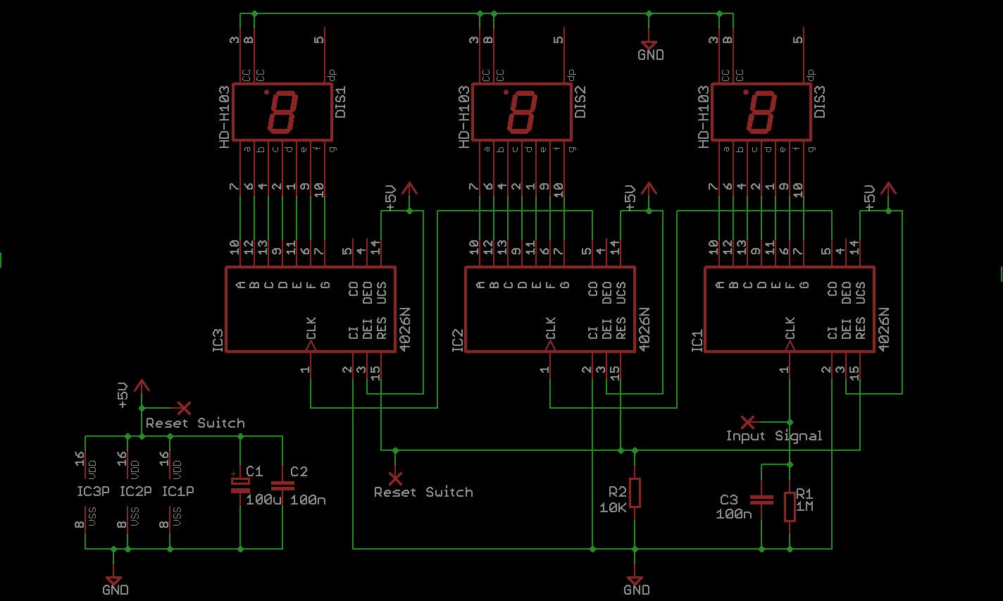
I wanted a counter that would basically count from a input signal, such as a reed relay to count the turns when winding a transformer or inductor for example. so I came up with this. I limited it to 3 digits (so it counts up to 999) because I only had veroboard big enough for that many but technically I don't think there is a limit to how many you can cascade because the CD4026 basically counts to 9 and sends out a clock signal on ten to the CLK in on the next chip
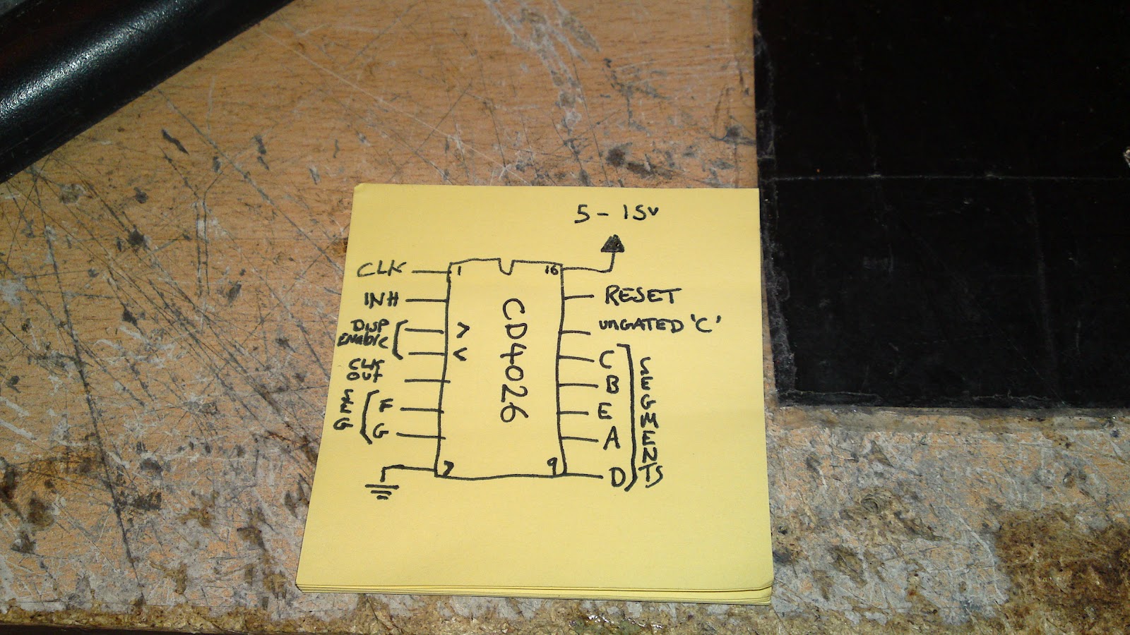
quite a simple circuit in theory but a pain in the arse with the jumpers and stuff, in order to try and save space I made jumper rails with little wire hooks which I've drawn on a little post-it note to try to show you what I mean, though I do tend to put the jumper a lot closer to the board than the diagram shows of course!
while building this up, I came across the issue where if I touched it, it would start counting up rapidally - this was because my body was acting as an antenna for 60Hz mains hum which can be an issue sometimes so I added a little R C bit to stop this and this also served to make it reliable when using a push-to-make switch to count on it.
if you want the exact LED displays I used it was this one LED DISPLAY but any common cathode display will do as long as the pinout is the same (shown below
Wednesday, 30 May 2012
Logic Probe Stripboard Veroboard
quite a simple and boring little thing, but an extremely useful bit of test gear so I urge you to build it. I actually laid out the veroboard to fit inside the little tin in the picture, I had envisioned it looking a lot better than it does but I am quite frankly shit at enclosures whether they are old mint tins or proper ones from the shop.
when you've built up this circuit, to use it you connect the power clips to the power of the circuit you're testing and probe the logic outputs.
you'll notice that when you power it up and the probe is not touching a test point all the LEDs are lit up, once it detects the actual logic level the LED (high or low depending on the logic output) will light up and the others will go out.
Subscribe to:
Posts (Atom)