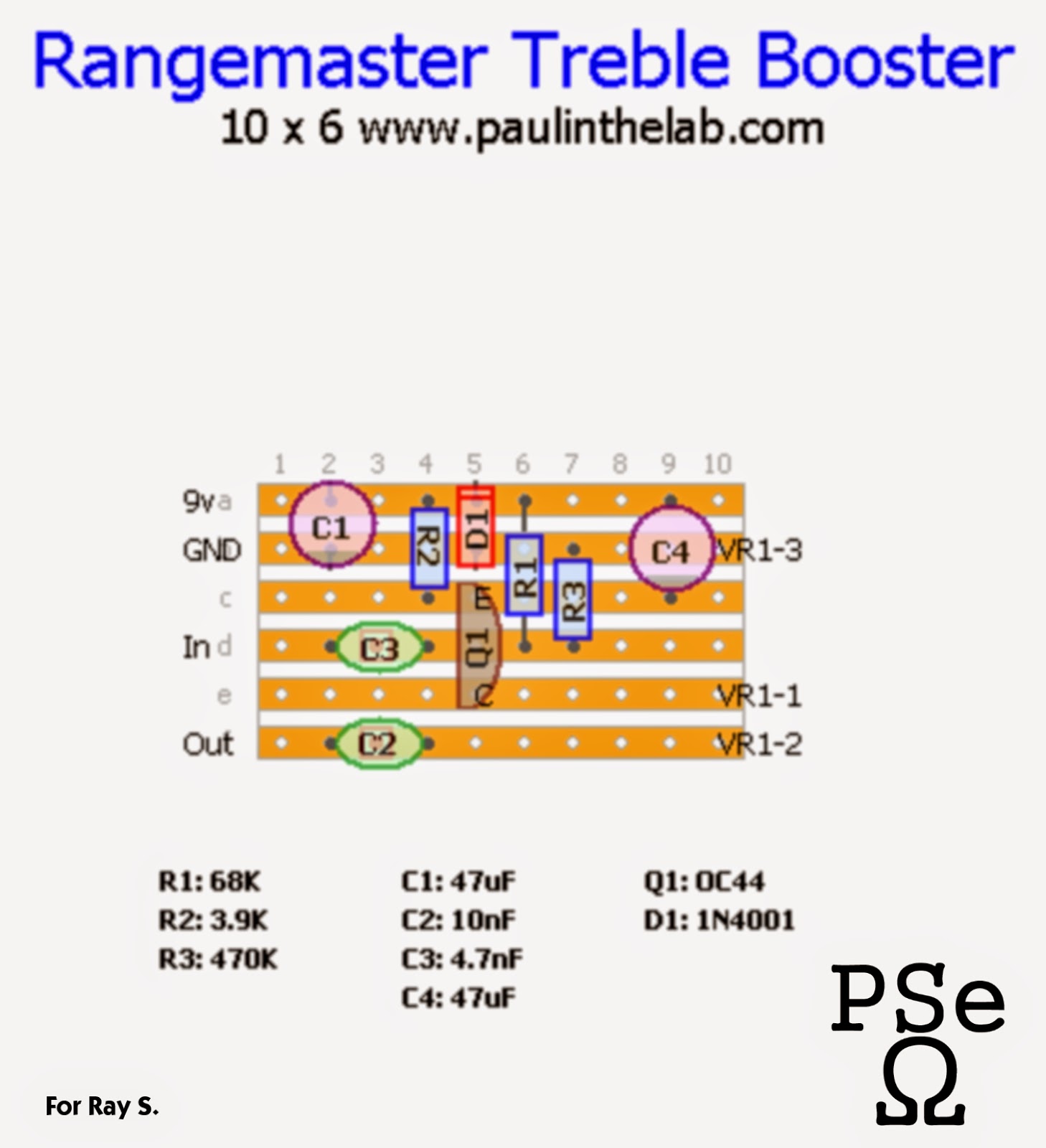
the 2nd Offering in "Treble Booster April" - the Rangemaster. I used the AC128 transistor in mine primarily because I didn't have any OC44s left I also added a 1N4001 diode to protect the circuit against reverse polarity - no, it doesn't change how it sounds and yes, you can leave it out if you don't believe me.
I know the 5nF transistor can be difficult to find so in the actual layout I put 4.7nF capacitor but given the nature of capacitor tolerances a 5nF rated capacitor would probably measure that far out anyway.
anyway - this is a lovely treble booster and I even used it in the song posted below so you can hear it in action.

hi Paul, your blog is truly inspiring!
ReplyDeletecan you please provide some working voltages?
i think i got working, but it doesn't boost that much, and it gets silent when the pot is at max. position.
regards,
george
I think you've wired the pot back to front - it should be silent at min position.
Deletethis kind of thing doesn't boost much - you put it in front of your amp cranked up loud with a bit of gain on the amp and you
get that nice Queen sound
Thank you Paul!
Deletei have got a working treble booster now.
regards,
george
Aha, my next build. I love your Greg Fryer TB and I have an AC128 doing nothing. I'm also super keen on Brian Mays 70's tone. Speaking of which, there seems to be a lot of people (including myself) that are chasing the Brian May sound. I've read a lot about AC30s, normal channels turned up to 11 and treble boosters but people seem to overlook the modulation. In the 80s I know he favoured the BOSS CE range but I love his 70s tone, especially the Foxx Phaser. Paul, have you ever fancied having a go at this (http://dirtmonkey.org/foxx.png)? Probably a bit much for Vero though.
ReplyDeleteGreat site and great layouts!!
I would suggest building this one http://www.paulinthelab.com/2014/04/brian-may-treble-booster-stripboard.html
Deleteit's the one his dad made for him when his rangemaster got stolen. (actually I would recommend building both of them)
I have made the foxx phaser in the past but that was before I started this site so I don't have the layout anymore. I've experimented alot with phasers including replacing the onboard LFO with a voltage control so I can control the phasing with an old wah pedal shell.
Brian used the CE-2 and if you get the CE-5 it is the same circuit with the addition of a filter which is removed when you have the filter knobs upto full. (I believe you can get that pedal quite cheaply - I know I did, I have a CE-2 aswell, I am a big chorus fan)
he did tend to use the AC30s for live use more than the studio - he preferred the Deacy for the studio (that's another project on my site!)
I am a very big Brian May fan as you can probably tell!
Another Treble Booster, that will be three in a week after building the Rangemaster and the Greg Fryer - Now onto the Harold May! I'll be doing the Deacy soon too!
ReplyDeleteI've got a Behringer C0600 which is an unashamed clone of the CE-5. I really like it too, but without comparing directly to a CE-5, I'm not sure how good a clone it is.
Did you have a look at that Foxx Phaser schematic? Is it any different to what you built? I'm trying to copy it to Eagle PCB software to create a PCB layout (looks a bit much for Vero). Do you know what the opamps and diodes should be. I know it uses 2N4302 or PN4302 transistors. I'm also hoping to take out the foot bit too.
Thanks for another great build. The Rangemaster is a bit noisier than the Fryer but also great.
Update: I've managed to build a fOXX phaser clone and even though my skills suck, it sounds authentically awesome.
ReplyDeletehttps://www.youtube.com/watch?v=hiqZ8-lvY9E
http://www.diystompboxes.com/smfforum/index.php?topic=110315.0
Man! your song is just beautiful!... awesome work dude!.
ReplyDeleteSorry for being a bit ignorant, but what does the "vr1" in the layout stand for? Is it the pot? What pot should I use? I want to build one of these!
ReplyDeletevr stands for variable resistor, that's your 10k logarithmic pot as shown in the schematic.
Deleteregards,
george
Thanks! I guess I should learn to read the schematics and not only the layouts... :P
Deletehello. ive made this as you've shown us but i cant get a led to work with it.
ReplyDelete1. if i give a normal polarity from the battery the sound with the effect get a little boost but the led it not working.
2. if i give a reversed polarity from the battery the effect kills the guitar sound but the led works perfectly.
in the 1 attempt with normal polarity i tried reversing the led but it does not work at all and the voltage measured from the effect +9 & ground comes out as 0.8
whats going wrong?
i didnt have oc44 so i used SFT 308 bought from ebay.
could you help me please? maybe provide us with wiring draw for input, output, voltage jack, 3pdt switch and led?
Thanks alot!
hi, you can follow the first graph @ this link http://tagboardeffects.blogspot.gr/2012/02/offboard-wiring.html
Deleteor any other alternate wiring schematic for negative ground effects (almost standars these days).
regards,
george
hello and thanks.
ReplyDeletethere was some kind of problem with the diode and when i removed it the pedal now works great.
Alhought im running it on a battery that keeps dieing and i cant hear its sound that well.
Could you please tell me what mA should the 9v inverter have?
Thanks and also thanks for the wiring schematics!!!
Euxaristw!
hi, this is a standard negative ground pedal (center negative supply / battery), you don't have to invert anything. the diode is for polarity protection, i.e. when you try to plug in the battery the worng way. (also the Rled connects +9V and the positive side of the Led diode).
Deletei am not an expert but i think the pedal draws a tiny amount of current, a 9v battery should last for months, so check your stripboard for unwanted connections between the copper lines and doulbe-check the pinout of the transistor.
regards,
george
I built this correctly as shown and it sound nice!
ReplyDeleteWhen i play the guitar straight to the amp it plays at about 10/10 (volume). When i plug it throught the pedal the volume drops at about 9/10 while getting the effect of the pedal. Why?
Whats wrong? Isnt this supposed to boost my guitar?
Is it 1/2 watt resistors ?
Thanks!
the "booster" refers to the treble aspect of it - it cuts a lot of low-end signal and overdrives the treble/harmonics so it's normal, you just need to turn your amp up.
Deletethe idea with this circuit is that it's always on, it was never designed to be bypassed that's why people like Brian May have it attached to his guitar strap and you see him messing with his guitars volume pot during his concerts.
yes but seeing the original effect on youtube review actually works completely different. i mean i could name the effect i built jazz amp but for sure no booster. it makes the sound of my guitar suitable for jazz with low volume on amp. arent there a few things i should have in mind before building this? like for example the watt of resistors, the volts of caps and their material?
Deletei was amazed at how different it sounds from an original and the volume cut? oh im so confused.
Hi Paul. I am trying to make this pedal so i can use it on my pedalboard together with my other effects(center negative/ground). Also with a 3dpt switch for true bypass, LED and anti pop resistors. Can you please check my scheme i made and check if it's correct ?
ReplyDeleteThanks you so much.
https://www.dropbox.com/s/657c6auqpic7p6o/Rangemaster-Ludeco.png?dl=0
Thx for the schematic! I Just build the treble booster. Sounds awesome 💪
ReplyDeleteI am getting a siren-like howl when I engage the effect. Built it according to the layout, with power supplied via adapter regulated power supply with no other effects in chain.
ReplyDelete