I'll start this off by saying I'm not that keen on record players but last night I dusted off my old Garrard turntable and promptly realized my amplifier doesn't have a phono input which meant no RIAA de-emphasis equalization. Or in other words my records would sound like shit.
So I opened up eBay to buy one - then I remembered that I know how to make things so that's what I did.
I didn't do it for the site specifically but I thought I should share it with you people in case you ever have this problem. I also used top quality parts such as the OPA2134 op-amp - this is the perfect type of application for this part - it is an op-amp designed for the full audio range.
as a side note - read the product reviews for this IC on the texas instruments page - some of them are hilarious - here is one quote "Replace those TLO72 with these and the difference is huge! (extended low end, smooth mid-range airy top end)"
people really like to talk a lot of shite about things that are not there! - this is a very low noise op-amp optimized for the audio frequency range. if it made things sound "extended, smooth and airy" then it would be a poorly designed product.
Anyway - if you don't want to spend a load of money on a OPA2134 or you want to try it with a cheaper op-amp any audio dual op-amp will do. I tested mine with a RC4558 (cause it was nearer than the OPA2134)
it is powered by a 20 volt supply, though I'm sure it will work at lower voltages.


FYI - it's worth splitting the curves of the RIAA correction into separate stages. If you do the HF part first, you get a strange result - scratches and surface noise are significantly reduced! I couldn't understand why this should be until I realised that the scratches are very fast rise-time transients: rolling off the top end first (before applying the bass boost part of the correction) means that the second stage (the LF correction) doesn't get to "see" these fast transients and suffer from transient distortion.
ReplyDeleteTo further check my theory, I built a couple of RIAA stages - one with the LF correction first and another with the HF correction first. The difference was astonishing!
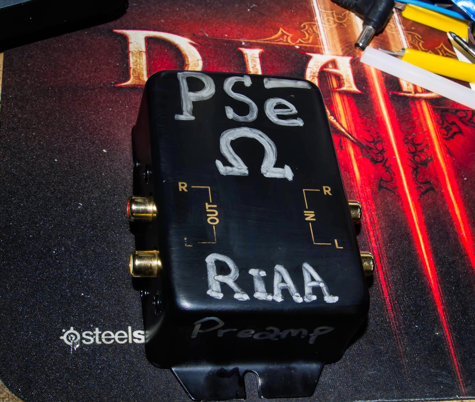
There's little point in using esoteric, expensive op-amps for RIAA stages - the inherent noise from the record itself will massively outweigh any contribution from even a cheap TL072! I do select the resistors and capacitors with a meter to match (approximately) them channel to channel, but don't bother with "mojo" parts - the cheap Far Eastern "green polyester" capacitors and ordinary 2% metal film resistors are perfectly good enough. I battery-power the RIAA pre-amp (the consumption is just a few milliamps) - I used six cheap Lithium-ion 5V cell phone batteries for +/-15V rails, and fitted a charging socket to the box that the thing is built into. I used reasonable quality phono sockets for the inputs and outputs, and a small DPDT toggle switch to switch the power.
Many "golden-eared" reviewers have heard records played through my 2-stage RIAA circuit, and all remark on how "quiet" it is!
I only used the OPA2134 because I had a load of them sent to me from TI for this blog - I'm not a fan of mojo shit as I described in the post accompanying the project
DeleteThis comment has been removed by the author.
DeleteHey Paul, would this work with a power supply from a laptop?
ReplyDeleteaye but just be sure you check the wires - some laptop supplies have 3 wires instead of 2
DeleteI was just gonna go with one that has a boss type plug end. I figured it would work okay, heh I use one for a 25 watt solid state amp that I made to power some stage monitors that I keep in the shed to listen to music on while working. Thanks again Paul!
ReplyDeleteHah if you ever get bored and wanna design an RIAA phono pre that is of good quality and uses tubes I'm totally down for making one. I have a hard-on for tubes (not necessarily for the sound.. I just really dig how they look all glowy and sexy..)
ReplyDeleteHey Paul, very nice work ! It's cool to see someone cutting the BS from all the other schematics we can see floating around from the web ;)
ReplyDeleteI have some questions:
- where did you get the R & C values for your RIAA equalization ?
- I guess that you use a single supply with a virtual ground ?
- And most of all: does it sound good ?
Thaaaaanks !
cheers - I'm always quite annoyed by audiophile nonsense!
Deleteanswers...
1. I used a calculator, it took ages. I'm sure there will be versions of this with the same
or similar values but I wanted to double check since this is the type of thing where people alter things
through the years.
2. yes, that's why there is a separate "audio ground"
3. it certainly does, I play my Queen records through it.
9v boss type power supply should work fine, shouldn't it?
ReplyDeleteThat's kinda a good question. I built this today and am almost ready to test it. Still have to get some rca jacks before I can move on to that, but I will hook up 9v and see how it does and I'll report on it immediately after.
DeleteI am of no help.. I suck at vero and only managed to make a smoke generator/IC melting apparatus. I will try again later.
DeleteI burnt an IC up in smoke too ... I almost discarded Paul's design, until I checked everything and tried again with a new IC and VOILA ! It works perfectly !
DeleteThanks again for sharing Paul, it sounds very good and the veroboard is very compact, which is perfect for my project.
I have burned many ICs in my time - what was the issue when you checked? a bit of stray solder?
DeleteI don't know, maybe ... I checked everything with a OHM-meter: connections, strips, cuts... I was so surprised when it finally worked !
DeleteHi,
ReplyDeleteI was planning to stick this inside my fathers old turntable so he can connect it to his home theaters aux input. That audio groud/virtual ground confuses me. Do I connect ground from DC jack to GND row and ground wires from audio cable to AUDIO GND row? Thanks!
Hey Tommik
DeleteI was wondering the same thing but I would be assuming so. I'm going to build it up and give that a whirl. Not too much can go wrong.
My main question though is about C9 and C10, the schematic says 470uf and the layout says 470n (0.47uf). I'm guessing they are 470uF but was hoping someone could confirm.
:)
they both say 470uf
DeleteOh dear, my apologies Paul. After looking closely I see what I thought was an n on the schematic is indeed a microfarad sign. 470uF caps, get in my trolley. Thanks Paul!
DeleteHello Paul, I'm almost ready to build my own; before trying your design, I would like to know if the 47uF value for C2 & C5 is crucial, and if I could use other values. Thanks !
ReplyDeletethey are crucial values - they are part of the filter
Deletei am willing to try this preamp but i want to ask you if you can post a picture with the whole finished assembly. i am really a noob when it comes with circuits and i want to see exactly how and where the rca plugs and the power plug are connected. i really can't figure it out form the breadboard picture. thanks in advance.
ReplyDeleteI bought, glued, fed, and works impeccably with lm833 that i had at hand...I will try a opa2134 later.
ReplyDeleteGood job and ty .
Happy new year from Romania!!
This comment has been removed by the author.
ReplyDeleteThanks for sharing this Paul.
ReplyDeleteSounds great!
I mostly build guitar pedals and tube amps and don't have many fancy ICs. JCM4558 worked fine for me and I used 12v supply.
Also tried JCM4580 and TL072. They all sound the same, but other than the JCM4558 there was (a very minor) distortion sometimes.
I am happy as it is but I might try 20v and OPA2134 later.
I have now tried with 18v.
DeleteI also tried OPA2134PA.
No apparent difference. Still happy with this phono preamp, just a bit poorer than before I tried fancy ICs and poser supplies :)
Thanks Pual, sound great very clear and airy.
ReplyDeleteThank you for sharing !!!
ReplyDelete