I've done a similar adjustable load before but I've tweaked this one a little so it performs better and so on.
PSU UT = power supply under test
the one I made can sink over 2 Amps. you just need to make sure you have a big heatsink.!
it's also a good idea to mount the big resistors offboard cause they get hot.

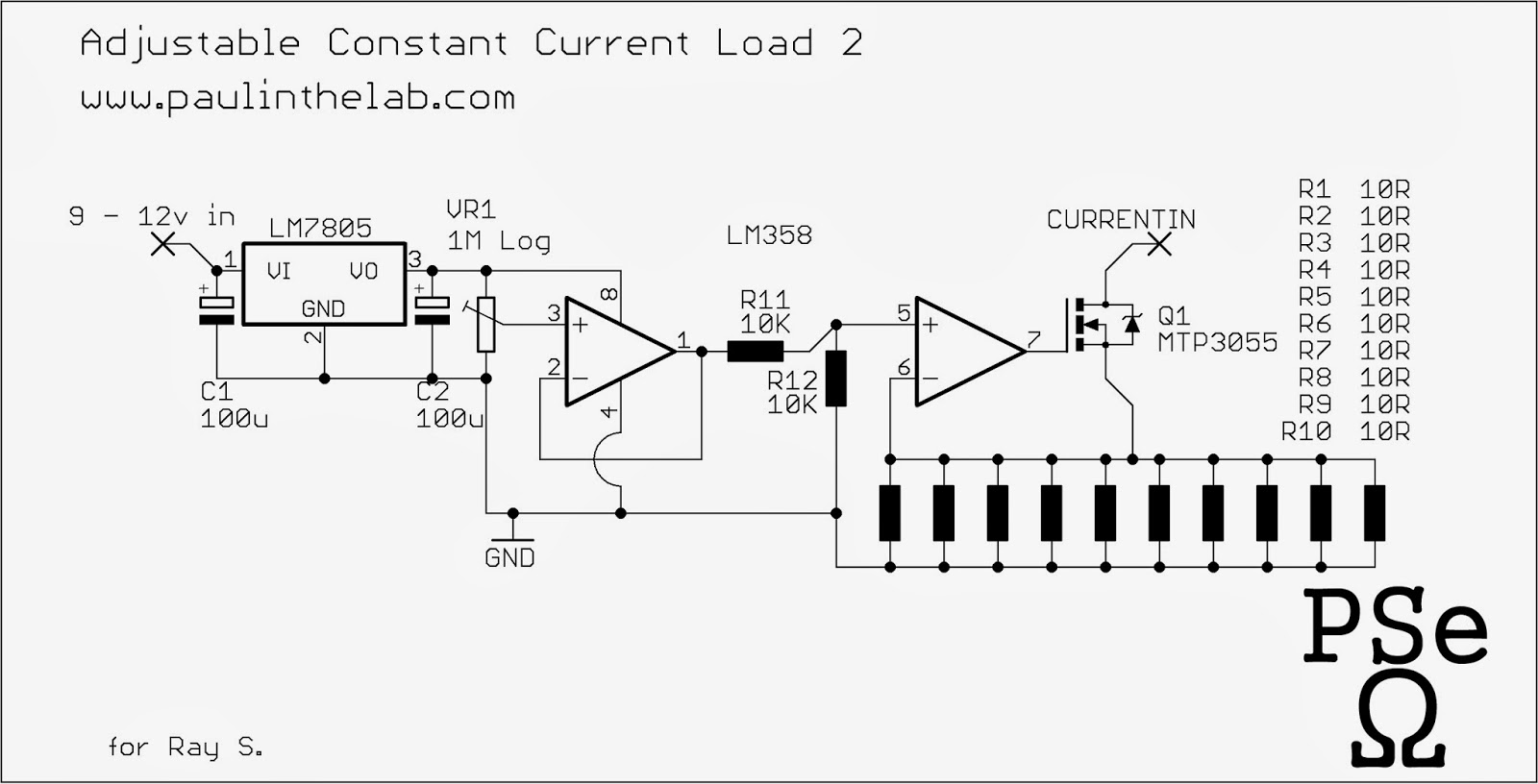

The resistors i do have are 1% 10ohm. They are very good quality. I don't get any load drawn Nothing happens. What to check? Doing some testing and where? Thanks vince
ReplyDeleteI would check pin 8 is around 5 volts for a start.
Deletealso you have to connect this circuit to the ground of the power supply under test
i did not connect ground from power supply under test, ok. ok i check the pin 8. and report back. thanks Paul. Vince
Deletei am sure your circuits work. All that i built from you have not worked? The dancing music leds. It turns on but no output from the op-amp. Thanks Vince
ReplyDeleteI am using a elcectric mike. It was a good working mike, what else could i use in place to check if i am getting a responce to the cd4017's. I can take pictures and email. ok thanks vince
ReplyDeleteone thing I remember about that layout is that I had to put the 2 logic ICs upside down - so make sure you've done that (I'm sure you have)
DeleteI used one of these mics http://www.openmusiclabs.com/wp/wp-content/uploads/2011/03/mic_start_small.jpg
but if you briefly short the mic input leads that should activate it - if that works then it's probably the wrong type of mic - the right type is of course a free one ripped out of an old tape recorder
yes i put the logic IC's upside down. I had to take a closer second look. Yes i get 5 volts at pin 8. I will look and report back for the Dancing leds next. Thanks Paul. What next? Do you think i got the wrong logic transistors? Vince
ReplyDeleteTTP3055? I am goin to get another 3 pcs soon and try it again. I am not building your 9 volt battery tester tonight. I just finished your Dark flashing led. Works. no problem there. ttyl
ReplyDeletei am now building your 9 volt battery tester. Oops not = now vince
ReplyDelete