Welcome - Please Read

Welcome. I wanted to provide stripboard layouts I've made to help people new to electronics and even the more experienced get into different aspects of electronics.

I verify the layouts before I post them.

My Facebook Group: www.facebook.com/StripboardLayouts - Please Add For Updates!
My Twitter Thing: @InSonicBloom

Friday, 21 June 2013

Simple LED Flasher Stripboard Veroboard Layout


I've done LED flasher type circuits before on here but usually they were for something someone wanted so they did specific things like fade in and out and so on.

So I thought for a little 10 minute project I would do one of the very first projects I ever made as a little boy. I was very proud when I made my first LED flash. it's not like now where people just load up the "blink" sketch in Arduino. this is a proper old school relaxation oscillator.
my original one had a few more components but I've managed to whittle this down to 3 resistors, 2 transistors and a capacitor + an LED obviously.

this particular circuit is known as a relaxation oscillator and there's lots of theory and stuff behind that but in extremely simple terms: it charges a capacitor until something "disturbs" it. in this case the "disturbance" is the threshold voltage of Q2 (the voltage at which the Base conducts) this quickly discharges the capacitor which results in a short blink.
which looks nicer than the conventional square wave oscillator which the LED stays on the same length of time as it is off

everyone loves a flashing LED


if you get this reference then you're ace.

Thursday, 20 June 2013

Adjustable Lab Power Supply With Current Limiting ( L200C ) Stripboard Veroboard Layout


it's been a while since I've done a new layout - I've been and continue to be ill but I thought I would try and do something so people don't give up coming here. so with a body full of painkillers etc. I designed this little power supply.
it differs to my previous power supplies in that it is an extended range one. IE it goes from 0 volts upwards rather than 1.2volts upwards.
the way this is done if by creating a negative reference voltage and feeding it into the L200C regulator.

this also has current limiting so you can set it to drop out if a circuit tries to draw more current than it should (due to short circuits etc.) which can avoid circuit catastrophes.

anyway here you go.


Wednesday, 10 April 2013

Soft Latch True Bypass (Relay) Switch For Guitar Effects Stripboard veroboard Layout


People often like to retrofit their guitar effects with "true bypass" switches but this usually means wrecking the pedal case by drilling holes in it and stripping out the buffered section etc.

Personally I don't like doing this modification, I like there to be a buffer because there is always a degree of signal loss in pedal chains but this is here for those who do like to do it.

as it uses a mechanical relay (which can be found at Rapid Electronics or wherever - the one I used is the 12v version of this one ) it is exactly the same as a true bypass switch and adds nothing to the signal.
it is quite small so it can fit in some pedals (like a tubescreamer) or you could use it externally to maybe bypass a whole group of pedals (or just one of course)

it's worth mentioning that this has many other uses such as controlling high power relays with a little tact/push switch and so on

NB: if you find you're getting misfire clicks you can make the capacitor a higher value - that part acts as a crude debounce - the higher it is the more stable it becomes but the slower you can turn it on and off but I found 220n was fine for guitar bypassing

hope you like.


for the purpose of perspective

Thursday, 28 March 2013

Nintendetar Guitar Fuzz Stripboard Veroboard Layout


This is something I made a long long time ago and subsequently made actual PCBs for which I still have but due to the fact my agoraphobia has reached such levels I can't post them anymore so I don't bother selling them. however it's a cool effect so I made a stripboard for it. I also Made an Add-on board a while back located HERE

or with the Oscillator Add On..


Wednesday, 20 March 2013

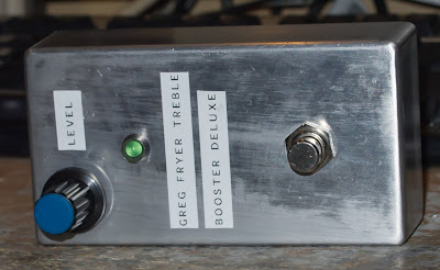
Greg Fryer Brian May Treble Booster Deluxe Schematic Stripboard Veroboard Layout


this is one of the best treble boosters I've built and I've built alot of them being a Brian May fan.
this was traced from the circuit board and I have made 2 changes (that don't affect the sound)

1. in the original there are 2 power supply capacitors (47uf and 33uf) in parallel which was obviously used to keep production costs down - Greg will have initially put in the standard 100 uf capacitor but if his other pedals/products used 33uf and 47uf caps - it would have been cheaper to just parallel a couple of those up to get near enough.

2. the other change is that there are 2 10pf capacitors in series again this will be a production cost thing - it would be cheaper to use 2 10pf capacitors in series than adding 1 4.7pf cap to the build (if he used a lot of 10pf capacitors in other builds which he most probably will do.)

so with those changes noted: it sounds no different to the original unit but you can always swap them if you don't believe me.


Friday, 22 February 2013

Sparky 5 Watt Amplifier Stripboard Veroboard Layout


I thought it was about time to tackle something that's been on my todo list for a while and that is to make a follow up to the infamous Ruby amp (made by Runoffgroove.com) which is a popular circuit among the DIY community.

So I thought the best idea was to use an amplifier IC in the same family as the Ruby's amp IC which after an extensive 5 minute search on Texas Instruments website lead me to the LM384 (DATASHEET) which is a 5 watt mono audio amplifier.
it needs a minimum of 12 volts to run though I would run it at 15 volts

All the way up it goes into crazy distortion but before that it is a really nice sounding amp, you get a nice clean and then the louder it goes the more it clips - but nicely - I must do some sound clips!

it powers a 1 x 12" cab very nicely - I've not tried it with a 2 x 12" cab yet but I think it will be fine.

so I introduce to you the SPARKY Amplifier - why did I call it the "SPARKY"? fuck knows, I think it was cause I was watching that cartoon where the piano comes to life.


Wednesday, 20 February 2013

Yamaha NE-1 Bass Parametric EQ Preamp ( Nathan East ) Stripboard Veroboard Layout

I'm not feeling too well so I won't drone on about this + I'm going to watch Michael Mosley documentaries for a bit.
My friend has been asking me to do a layout for the Nathan East Bass Preamp since his got stolen at a gig some years ago so I finally got around to doing it - I had to reverse engineer from pictures on the internet and it has been somewhat a pain in the ass however it now works and sounds how it should.

I didn't have the required TL062 op-amp to hand so I used the TL082 (DATASHEET) in this application there will be little to no difference to the sound - the sound is altered in the components around the amplifier.

one thing I should mention is that some people mod it by changing C4 from 47p to 220p ( I think so they can use it with their guitars. Anyway - enjoy.

EDIT: I bought another one of these preamps and C4 was 100pf in that one - so it seems that they either changed it at some point or just use something other than the normal 1% tolerance capacitors you'd usually get in this type of thing 


Saturday, 16 February 2013

Self Powered 9 Volt Bar LED Battery Tester LM3914 Stripboard Veroboard Layout


another cool little voltage monitor but I had some requirements - I wanted it to be self powered and have an onboard load so I could check any 9 volt battery with it.
this is for a active pickup system so the self powered part of the design wasn't hard to factor in as usable voltage is around 5 ish volts in the EMG's I have.

and Last of all I wanted to use the LM3914 (DATASHEET) cause I've got loads of them from another project I never got around to doing.

I used a 82 ohm resistor (switched in by pressing the push to make switch) this will allow you to test the battery under a normal load which will give you a better indication of the batterys chargethe 82ohm resistor draws almost 110mA

I have done a circuit like this before which was a 0 - 10v voltage monitor (HERE) but the difference between that one and this is that this one is powered by the battery you're testing and the other one though more accurate needs a second power supply.


Saturday, 2 February 2013

Amplifier Speaker Load Box 16 ohm For Direct Recording


I wanted to use my Bugera 6262 cranked up a bit so I thought I need to design a quick load box so I can unplug the speakers and put the line out into my recording interface and use software based cabinets.

There isn't a layout per se but I've provided a schematic and pictures - it is a very simple design so you should be able to follow it easily enough.
you will also notice that it uses 2 100watt 33 ohm resistors in parallel which will allow you to use amps upto 100watts or in my case (130watt) an amp not turned all the way up

you need twice the power rating on the resistors as indicated on your amp - ie if your amp is 50 watts you need 100watt resistors.


Friday, 25 January 2013

9v Fast(ish) Battery Charger Stripboard Veroboard Layout


most of the chargers I own don't work fast enough - they take in the order of 14 hours so I thought "why not make one" since I have about 30 things with chargeable 9 volt batteries in them it would be nice to make a few of these. Anyway I wanted to make one that automatically cut off but it got a bit messy so I figured I would just drop the amount of current going into the battery so I could just leave it going for a few hours.

to work out charge time: hours = mAh / mA
example case: a 9v battery I have is rated at 150mAh
150 \ 50 = 3
therefore 3 hours

the LED illuminates when the battery is connected

the Transistor (BD135) needs to be heatsinked but the LM317 doesn't so if you're using a metal case you could just screw the transistor to the case and use that as the heatsink