Welcome - Please Read

Welcome. I wanted to provide stripboard layouts I've made to help people new to electronics and even the more experienced get into different aspects of electronics.

I verify the layouts before I post them.

My Facebook Group: www.facebook.com/StripboardLayouts - Please Add For Updates!
My Twitter Thing: @InSonicBloom

Showing posts with label Test Gear. Show all posts

Tuesday, 4 August 2015

Very Accurate 10volt and 5volt Reference For Testing Multimeters etc. Stripboard Layout


I thought this would be a good project to keep around to see if my digital multimeter has drifted out of calibration.

I power it from a normal bench power supply but it would probably be better if you used 2 9v batteries in series.

The LED on it displays when over 100mA is being drawn from it - basically if the LED is lit disconnect it or things will be getting very hot!

I tested it in free air with open windows over 2 hours and it was very stable so I can rely on it.

Linear Tech do a few different drop references for this IC
the 2 I've tried are the 10 volt reference and the 5 volt reference
the part numbers are
10 volt reference; LT1021BCN8-10
5 volt reference; LT1021CCN8-5


it stayed at 10.0006 for over 2 hours - the least significant digit moved around but that's 10's of uVolts!


Friday, 17 July 2015

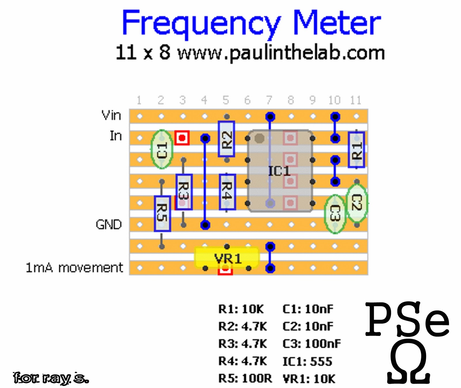
Frequency Meter Stripboard Layout


I built this as a rough frequency meter to make sure a bunch of oscillators were oscillating in the right ballpark frequency.
it uses the lovely 555 timer IC.

it responds best to squarewave signals (maybe triangle too, I forgot to test it with triangle waves)


Tuesday, 14 July 2015

Quick And Dirty Laser Driver Stripboard Layout


This was just a quick little circuit I built to test all the salvaged CD/DVD lasers I have.
essentially it is a adjustable constant current power supply.

the Vin is 7.2 volts.


Sunday, 20 July 2014

Simple Dual LED Battery Monitor stripboard layout


I got some 3 pin dual LEDs and I thought a good use for them is as little 9v battery status monitors for my guitar pedals. so I came up with this quick circuit that fades from green to red as the battery voltage drops (as shown in the video)

it's a good little mod circuit for any project you want to build that uses a 9 volt battery (or existing stuff you own)


Sunday, 27 April 2014

EMF Ghost Detector Stripboard Veroboard Layout


I'm not a big believer in ghosts and all those paranormal reality shows only ever seem to film ghosts with no other aspiration than to knock on stuff however EMF is something I find interesting because we're surrounded by electro magnetic radiation (whether or not you believe it's paranormal is up to you) and I wanted to build a EMF detector - so I did and here it is.

there is an audio output so you can hear/record the actual EMF being displayed on the meter.
it's quite important that you have the pickup inductor mounted away from the device (as you can see in the picture) because you don't want to pickup the EMF of the device (not that there's much of it!)

so if you go out ghost hunting with this - make sure you send me the pictures of the places you're hunting cause I love abandoned places.
and if you record anything weird send me a link!


Saturday, 1 February 2014

Acoustic Probe / Electronic Stethoscope ( based on Robert Penfold Design ) Stripboard Veroboard Layout


I was trying to track down a noisy inductor (I like to call them a squealer) in the back of a monitor so I thought I would design a electronic stethoscope - then I remembered I had one from something I built from Robert Penfolds article in a practical electronics (silicon chip magazine for people in other countries) magazine in my youth. so I checked my box o'junk and found that I had salvaged parts from it.
So I made myself a new stripboard layout and built a new one. I had to change the odd part cause the original called for stuff that costs stupid money by opportunist eBayers.
But it works a lot better than the old one ever did - so hurray for opportunists I guess.

I use this to drive a pair of in-ear headphones and it really does work really dam well. so if you need something to track down the source of noise or spy on people through the wall or something - this is for you.

NB: if it's a bit too hissy for you - you can remedy that by putting a 1n capacitor in parallel with R6


Saturday, 30 November 2013

Adjustable Load Stripboard Veroboard Layout


I've done a similar adjustable load before but I've tweaked this one a little so it performs better and so on.
PSU UT = power supply under test
the one I made can sink over 2 Amps. you just need to make sure you have a big heatsink.!

it's also a good idea to mount the big resistors offboard cause they get hot.


Wednesday, 2 October 2013

Logic Pulse Generator - Logic Pulser Stripboard Veroboard Layout


Often with projects that uses Logic devices such as previous projects like the devils drone sequencer or the Sound Activated Dancing LEDs you need to create a clock signal to make the logic transition from one state to the other. you don't want to have to deal with the clock (or oscillator) part of the circuit in the experimentation stage so you need something that is capable of creating a clock signal. This is just that piece of test gear.

it also uses the same power supply you're using to power the Logic ICs in question.

here is an example of a commercial version http://uk.rs-online.com/web/p/needle-point-probes/5375163/?origin=PSF_437277|alt

aswell as the layout and schematic - I have included some oscilloscope pictures of what it actually does.

Sorry if my explanation is a little off today in the making sense department - I am suffering from cluster migraines and one of the symptoms is Aphasia. the important thing is that the actual layout and circuit are correct - which as you can see - is the case!


As you can see I have soldered a nail to the pulse output - I've found this is the ideal probe


Thursday, 26 September 2013

Adjustable Pocket Power Supply Stripboard Veroboard Layout

This is something I've been meaning to make for quite a while.

Basically the idea was that should you go around charity shops, car boot sales, yard sales, thrift stores and other such places it would be nice to have a power supply capable of giving you various voltages to check if things you are potentially going to buy actually work. the resistors are selected for 3 volts, 5 volts, 9 volts and 12 volts and you may notice that the resistor values (R2, R3, R4 and R5) are very specific and in some cases not available - these values are due to not being able to alter R1 when you switch the voltage.  

there are 2 ways to get around this

1.add resistors in series or parallel eg. for R5 I put 2K and a 68r resistor in series and that was near enough to get me my 12 volt output

OR..

2. use 5K/4.7K trimpots and calibrate with your DMM - using that method you can of course easily set it for voltages you think you will need the most.


Sunday, 28 July 2013

Poor Mans Audio Signal Generator Stripboard Veroboard Layout


this is something I made in school 15 odd years ago. you had to take a square wave, use a passive filter network to convert the signal to triangle and sine - this also has square and integrator waveforms. it's quite good up to 1 KHz but after that it starts to clip and go funny but it's more than adequate as an extremely cheap audio signal generator using 2 transistors and 1 LM555 timer IC - if you've gone through alot of my projects you'll notice how useful this IC is by now.

I have done another signal generator project that uses a proprietary ICL8038 IC Project can be found HERE which is more fully featured as far as project function generators go but the IC can be costly in certain places where as you can go on the grey market (IE eBay china sellers) and pick up hundreds of them for next to nothing.


Thursday, 20 June 2013

Adjustable Lab Power Supply With Current Limiting ( L200C ) Stripboard Veroboard Layout


it's been a while since I've done a new layout - I've been and continue to be ill but I thought I would try and do something so people don't give up coming here. so with a body full of painkillers etc. I designed this little power supply.
it differs to my previous power supplies in that it is an extended range one. IE it goes from 0 volts upwards rather than 1.2volts upwards.
the way this is done if by creating a negative reference voltage and feeding it into the L200C regulator.

this also has current limiting so you can set it to drop out if a circuit tries to draw more current than it should (due to short circuits etc.) which can avoid circuit catastrophes.

anyway here you go.


Saturday, 16 February 2013

Self Powered 9 Volt Bar LED Battery Tester LM3914 Stripboard Veroboard Layout


another cool little voltage monitor but I had some requirements - I wanted it to be self powered and have an onboard load so I could check any 9 volt battery with it.
this is for a active pickup system so the self powered part of the design wasn't hard to factor in as usable voltage is around 5 ish volts in the EMG's I have.

and Last of all I wanted to use the LM3914 (DATASHEET) cause I've got loads of them from another project I never got around to doing.

I used a 82 ohm resistor (switched in by pressing the push to make switch) this will allow you to test the battery under a normal load which will give you a better indication of the batterys chargethe 82ohm resistor draws almost 110mA

I have done a circuit like this before which was a 0 - 10v voltage monitor (HERE) but the difference between that one and this is that this one is powered by the battery you're testing and the other one though more accurate needs a second power supply.


Saturday, 19 January 2013

Floating Power Supply For DVM Panel Meters Stripboard Veroboard Layout


this was another one done out of necessity really.
I needed to power a panel meter from the same supply as I was measuring.
I actually didn't have the meter to test it with however it powered a cheap Digital Multimeter which I imagine takes up more current than a panel meter.
I also tried to make it small enough to be glued onto the back of the panel meter. 


Friday, 28 December 2012

Making A Current Blasting Power Supply With Old ATX Power Supplies


what is Current Blasting? I hear you ask..
Well sometimes when you have a fault with a piece of equipment it's not always easy to track down the issue - it usually comes down to a failed component that has shorted internally - a single failed component of possibly thousands so one method of tracking it down is blasting it with high current (at a low voltage)
It is quite a fun method of trouble shooting because most of the time the failed component explodes off the board, starts smoking or gets very hot.
so what's the best method of doing this? well get a high amp power supply which costs loads of money OR make one out of an old computer power supply.
You have probably seen people make power supplies out of these before for powering their projects which I don't personally think is that great of an idea because of the high current involved but you can use it for that if you wish.

The reason why these things are great for current blasting purposes is because the junked one I have (which is from a very cheap case that had a power supply on it) has a 5volt rail of 27 amps, a 12 volt rail of 13 amps and a 3.3volt rail of 25 amps. which as you can imagine is more than enough.

now for the usual "danger" crap...
I'm sure by now you're used to reading disclaimers and warnings to the point of being desensitized by it and it is easy to ignore these things.
but these things can be very dangerous so you need to take a lot of care when building/hacking these things. They have a lot of capacitors which may retain high energy even when the unit is unplugged. you NEED to make sure they are discharged before you start handling it - that goes for the filter capacitor on the IEC mains input - sometimes they don't have a bleed resistor and can discharge 240 volts (or whatever your local voltage is) into you which I can assure you bloody hurts.

2 Things you must be aware of to use these things

1. in order to switch it on you need to solder the Green wire to Ground (black wire) I suggest
doing this by means of a switch. The green wire will be labelled "PS" or "PSON" on the main PCB

2. some ATX power supplies need a minimum load to function which is around 200mA
to achieve this you must bridge the 5 volt and Ground terminal with a 22Ω resistor.

if you're interested in how this was worked out you can use ohms law
R(resistance)=V(voltage)/I(current) so you type into your Calculator
5 / .200 = 25 so you have the answer 25Ω and you round down to your nearest value which was 22Ω in my case


Anyway here are some pictures, if you have any questions don't hesitate to ask. 


Bare ATX PCB
very cheap supply I found in my shed


I found this on the net some time ago, I'm not sure who it belongs to so if it's yours let me know and I will credit you and your site

Thursday, 20 December 2012

Signal Injector / Tracer Stripboard Veroboard Layout


A quick but very useful project. I "designed" (I say designed, it's just a simple astable multivibrator with a basic transistor amplifier) 10 minutes last night and built it this morning basically to help fault find because I'm sick of having to fire up the function generator/scope when I just need a quick tester.
so as usual I will share it with you people.


Friday, 2 November 2012

Low Battery Indicator ( 9v ) Stripboard Veroboard Layout


I was in the middle of designing a little 9volt battery operated music thing and I thought it would be nice to have a little battery indicator to tell me when it was getting low.
Once I made it up I thought it might be a cool little thing to share on here so you could add it into stuff like guitar FX and so on.

it has 3 states:
1. if the battery is good then the LED doesn't light
2. between 7.5v and 6.4v the LED flashes to warn you it's getting low
3. below 6.4v the LED stays lit

I know there are specific ICs for this purpose however I like making my own "solutions"
Anyway hope you like it.


Tuesday, 7 August 2012

Dual Tracking Power Supply Stripboard Veroboard Layout


another project born of necessity (ie I blew my other one up) This is a 1.5Amp dual polarity power supply (adjustable)

This may look like a waste of stripboard however once you see how big the 1000u caps are you will realize that you need the room.


Saturday, 28 July 2012

Audio Function Generator Stripboard Veroboard Layout


there isn't really much to say about this circuit as it is mostly a 8038 based function generator with a few bits added on such as a DC-DC convertor for the bi-polar power supply and a range/shape selector switches etc.
the ICL8038 is rated to range from 0.0001Hz to over 300KHz however the sine on the one I built up stops becoming useful at about 300KHz and it starts at about 10Hz however this maybe because I exclusively use parts from broken stuff - the IC was harvested from a PEAVEY classic chorus amplifier that died years ago, The pots came from an old mixing desk and so on so you may get closer to the rated range however 10Hz to 300KHz is fine for most if not all Audio applications.

I should also mention the LT1054 DC-DC converter, I got this as a free sample from Linear Technology and I used this over the more common MAX1044/7660 ICs because I need 12+/- volts and the 1044 has a maximum rating of 10 volts.

Notes:
The ICL8038 does get quite hot
Make sure the capacitors are all rated at 35volts or above

Sunday, 22 July 2012

White Noise Generator Stripboard Veroboard Layout


This is a very basic circuit which consists of 2 parts
1st is the noise generator which is the first transistor with no collector connection
2nd is the bit which may look more familiar which is an AC common-emitter amplifier and this is just to bring the noise upto a usable level - I have taken a scope screenshot of what the noise looks like however it is an audible sound which is pretty useful for testing guitar fx or filters and other such things.

if you wish to learn more about the common-emitter amplifier the best source for information is "The Art Of Electronics" book - on page 77 almost the exact same amplifier circuit appears with explanation 

you can of course experiment with different types of transistor in the noise section - i'm not sure how available the BC108s are now, I just happened to have a load of old ones, I hit it with a hammer to get a bit more noise out of it.

the best voltage I've found to use this at is 18volts however it does make noise at 9volts upwards